A few months ago a friend of mine asked me if I could help him build a temperature monitoring solution for his home. After several failed attempts with various wireless temperature sensors/strategies I decided a wired solution was a better way to go. I built a solution based on an Arduino utilizing Maxim’s 1-Wire DS18B20 temperature sensors encased in off the shelf telephone jacks. The 1-Wire devices are low cost, require few extra components and can be networked together over a long distance. The telephone jacks provided a quick and easy well finished solution for cabling and networking the sensors together. The jacks also come with screws and double sided tape for quick and easy mounting. If you are interested in building one yourself read on…
Materials you will need:
- Phone splitter: GE 5 Jack Adapter (White) (Staples)
- Arduino Nano: Arduino Nano 3.0 NO-PIN (Gravitech)
- Phone jacks: Jasco 26526 Mini Surface Jack – White (J&R)
- Temp sensors: One Wire Digital Temperature Sensor – DS18B20 (Sparkfun)
- Prototype board: StripBoard preffered, perfboard is a little harder to use
- 4.7K ohm Resistors
- Mini USB cable
Sensor assembly instructions: (click photos to enlarge)
- Remove the cover from the phone jack.
![Remove jack cover]()
- Unscrew the red, black and green wires then cut away the plastic posts sticking up – highlighted in the photos by the black marks.
![Wires unscrewed]()
![Posts removed]()
- Cut a piece of stripboard so that it is about 1/4 of an inch smaller on the sides and end of the jack. Clip the edges of the stripboard along the end of the jack at a 45 degree angle, this will prevent the board from becoming stuck in the jack when you put the cover back on.
![Shape the stripboard]()
- Solder the DS18B20 sensor in place as follows. The flat edge of the package should be facing up when soldering to the board. Be sure to keep the leads through the board very short since the leads will need to be long enough to protrude from the jack once the cover is back on.
![Solder in DS18B20]()
- Solder the 4.K ohm resistor between the data lead (DQ) and the power lead (Vdd) and solder the wires from the jack to the board as shown. Tinning the wires before soldering will make it easier.
![Solder resitor and wires from jack]()
- Align the finished board as follows and gently bend the leads of the DS18B20 sensor down into the cavity in the jack base. Ensure that no leads from the sensor are touching.
![Bend the sensor leads down]()
- Snap the cover back on and you have a completed 1-Wire temperature sensor node. Repeat the steps above to build additional nodes.
![Finished Sensor top]()
![Finished Sensor bottom]()
![Finished Sensor front/back]()
Controller assembly instructions:
- Sorry, but I don’t have photos of the splitter before working on it, so the text will have to guide you here. Cut the existing 3 foot phone cable about 3 inches from the splitter then remove the cover. This might take some hard prying, but eventually the top and bottom will separate and the jack board will be visible inside. The phone wire will be soldered to the jack board and you can attempt to connect it directly to the Arduino, but in my case the wires were so small they snapped off while working with them. Remove the jack board to make it easier to work on. Ignore my already connected Nano in the photo:
![Splitter jack board]()
- Solder the splitter to the Arduino. The easiest way to do this is to ignore all the wire colors and connect a single sensor node with the cover removed to the splitter with an off the shelf phone wire (NOTE: Phone wires can either be straight trough or crossed over, it doesn’t matter which type you use, just that you use all the same type.) Once you have a sensor connected use your multimeter in continuity mode one at a time between the red, black and green wires soldered to the sensor and the wires attached to the jack board, this will allow you to identify and map the wires correctly to the Arduino.
- Test the board to make sure it is working correctly.
- Connect a sensor node
- Plug a USB cable into the Arduino and connect it to your PC
- Download the OneWire.zip file from http://www.pjrc.com/teensy/td_libs_OneWire.html
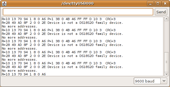
- Build the sketch and upload it to the Arduino
- You should see results similar to PJRC’s
![PJRC OneWire Library - Example Program]()
- Orient the Arduino as follows to slide it and the jack board back into the splitter case.
![Orient Arduino]()
- Fit the Arduino into the splitter case. Enlarge the existing hole from the phone cable removed earlier so that it allows access to the USB port from outside the case.
![Fit Arduino in case]()
![USB fit]()
- Snap the cover back onto the splitter and enjoy your completed 1-Wire sensor network.
![Completed project]()
Additional Resources:
- DS18B20 at Maxim (Datasheet): http://www.maxim-ic.com/datasheet/index.mvp/id/2812
- 1-Wire at Arduino Playground: http://www.arduino.cc/playground/Learning/OneWire
See my next post for something to do with all that new temperature data…
willnue


